What every column in an MBBR carrier specification actually changes in your design — surface area, hole count, density, pieces per m³ and dosing rate — with our full K1–K5 and PE01–PE08 data in one place.

MBBR carrier tables look interchangeable. They are not — each column drives a different part of your design, and quoting only one of them is how projects end up with a bed that will not fluidise.
Sets how much biofilm you can carry, so it drives treatment capacity per m³ of reactor. Higher is not automatically better: very high surface area usually means smaller internal channels, which are more sensitive to high solids.
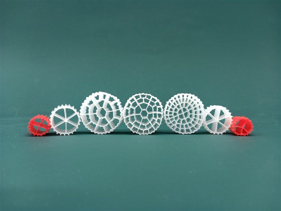
Determines whether biomass stays protected inside and whether the carrier fluidises properly. K1 has 4–5 holes; K5 has 64. Those two carriers behave very differently in the same tank even though both are "moving bed".
Must sit close to water so the bed circulates at a reasonable air rate without washing out or sinking. Our published range is 0.94–0.97 for the PE series and 0.96 for K1–K5.
This is what turns a volume order into a physical quantity, and it drives packing volume and freight. It also tells you how much surface you actually get per kilogram shipped.
You never fill the reactor 100%. Published suggested dosing is 15–67% of reactor volume, and your figure follows from the organic load and the surface area of the carrier selected.
Nitrification and BOD/COD oxidation rates are performance figures per m³ of carrier per day. Useful for checking a quotation — but they assume an acclimatised biofilm, so do not design to the top of the range.
The five standard models, with the published figures as supplied. Density 0.96, HDPE, service life over 15 years, operating temperature 5–60 °C.
| Model | K1 | K2 | K3 | K4 | K5 |
| Size (mm) | Φ10×10 | Φ15×10 | Φ25×10 | Φ25×10 | Φ25×5 |
| Holes | 4–5 | 6 | 19 | 37 | 64 |
| Surface area (m²/m³) | >800 | >800 | >900 | >1000 | >1000 |
| Density (g/cm³) | 0.96 | 0.96 | 0.96 | 0.96 | 0.96 |
| Pieces / m³ | >850,000 | >830,000 | >76,000 | >76,000 | >79,000 |
| Porosity (%) | >85 | >85 | >90 | >90 | >90 |
| Nitrification (gN/m³·d) | 400–1200 | 400–1200 | 400–1200 | 400–1200 | 400–1200 |
| BOD oxidation (g/m³·d) | 2000–10000 | 2000–10000 | 2000–10000 | 2000–10000 | 2000–10000 |
| COD oxidation (g/m³·d) | 2000–15000 | 2000–15000 | 2000–15000 | 2000–15000 | 2000–15000 |
| Pieces / kg | 2000 | 1100 | 520 | 320 | 500 |
| kg / L | 0.15 | 0.13 | 0.10 | 0.09 | 0.10 |
| Material | HDPE |
| Suggested dosing rate | 15 – 67 % of reactor volume |
| Film formation | 3 – 15 days |
| Operating temperature | 5 – 60 °C |
| Service life | >15 years |
| Unit | m³ |
| Packing weight | ≈ 125 kg/m³ (K5) |
| MOQ / price | On request |
The PE range gives finer steps between K models — from Φ10×7 up to Φ25×10, with surface area from over 600 to over 1,300 m²/m³.
| Model | Size (mm) | Density | Dosing % | Nitrification (gN/m³·d) | Surface area (m²/m³) | Pieces / m³ |
| PE01 | Φ12×9 | 0.94–0.97 | 15–70 | 400–1200 | >800 | >830,000 |
| PE02 | Φ11×7 | 0.94–0.97 | 15–75 | 400–1200 | >900 | >830,000 |
| PE03 | Φ10×7 | 0.94–0.97 | 15–70 | 400–1200 | >1000 | >900,000 |
| PE04 | Φ16×10 | 0.94–0.97 | 15–67 | 400–1200 | >800 | >520,000 |
| PE05 | Φ25×10 | 0.94–0.97 | 15–65 | 400–1200 | >800 | >118,000 |
| PE06 | Φ25×10 | 0.94–0.97 | 15–65 | 400–1200 | >600 | >118,000 |
| PE08 | Φ25×10 | 0.94–0.97 | 15–70 | 500–1400 | >1300 | >184,000 |
Service life for every PE model is over 15 years, material HDPE. Note that PE05 and PE06 share the same size and piece count but differ in surface area — a good reminder that size alone does not define a carrier.
The decision usually comes down to two things: how much solids your influent carries, and whether you are optimising for surface area or for channel size.
K4, K5 or PE08 give over 1,000 m²/m³. Best where influent is well pre-screened and you need the treatment capacity in the smallest reactor volume.
Fewer, larger channels stay clear longer. K1 (4–5 holes) and K2 (6 holes) have the largest individual channels relative to their size, which is why they remain the workhorse in heavily loaded industrial duty.
Because the bed has to fluidise within your existing geometry, the air system and the tank shape constrain the choice as much as the load does. Send us the tank drawing and we will check what will actually move.
Carrier is light and bulky. Pieces per kg and kg per litre tell you what you are really shipping — for the same volume, K1 ships very differently from K4.
The MBBR media calculation guide works the same method through a complete example with published rate figures.
Work in three steps, using the figures published above.
You need the influent and target effluent for BOD, COD and ammonia, plus the design flow. Capacity comes from the load to be removed, not from the tank volume alone.
Divide the load to be removed by the published rate for the model you are considering — for K1–K5 that is 400–1200 gN/m³·d for nitrification and 2000–10000 g/m³·d for BOD. Design toward the middle of the range, not the top.
The resulting carrier volume divided by reactor volume must land inside 15–67%. If it does not, either the reactor is the wrong size or a higher-surface-area model is needed.
Because geometry inside the carrier differs. It is a useful illustration of why a specification that lists only "Φ25 mm" is not enough to compare two suppliers — always ask for surface area, porosity and density together.
No. Higher surface area generally means smaller internal channels, which increase the risk of clogging in high-solids duty and can reduce how well the bed fluidises. Match the carrier to the load, not to the biggest number in the catalogue.
The published range is 15–67%. Your figure follows from the load and the chosen carrier's surface area — that is why we ask for influent and effluent targets before quoting a volume.
Physically yes, but the bed fluidises as a mixture and the effective surface area becomes an average. It is usually better to select one model per reactor unless there is a specific reason to blend.
On request. It depends on model and geometry, virgin versus recycled polymer, order volume, export packing and destination port — carrier is bulky and light, so freight can be a significant share of landed cost. See our price factors guide.
Published film formation is 3–15 days. Full nitrification acclimatisation takes longer, so plan for a gradual ramp rather than an immediate step to design load.
Send your water quality, treatment scale and target standard - we will confirm the right media, quantity and export packing.
Request a QuoteNo obligation - response within 24h (working days)